Thick Plate Laser Cutting Guide (20-40mm)
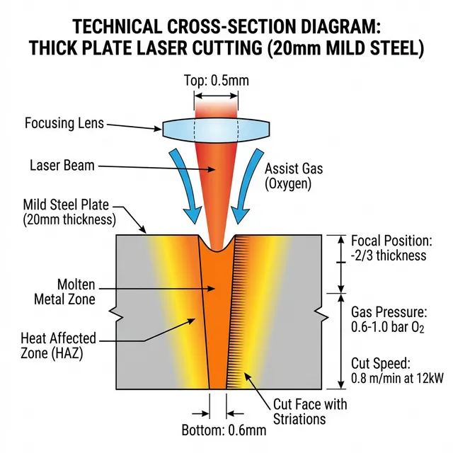
Cutting exceptionally thick plate (10mm-50mm) establishes the ceiling of fiber laser capabilities. It requires massive-power fiber lasers (12kW to 40kW), specialized piercing techniques, and stringent heat zone management. This guide covers power requirements, parameters, piercing strategies, and quality optimization for heavy structural steel fabrication.
Thick Plate Piercing Validation Path
For 20-50mm plate, validate piercing before optimizing straight-line speed. Record pierce time, spatter direction, top-side crater size, bottom dross, oxygen pressure, nozzle standoff, and lens protection condition before approving production parameters.
Power Requirements by Thickness
| Thickness | Minimum Power | Recommended Power | Typical Speed | Gas |
|---|---|---|---|---|
| 10mm Mild Steel | 6kW | 6-8kW | 1.5-3.0 m/min | O₂/Air |
| 15mm Mild Steel | 8kW | 10-12kW | 0.8-1.5 m/min | O₂ |
| 20mm Mild Steel | 10kW | 12-15kW | 0.5-0.8 m/min | O₂ |
| 25mm Mild Steel | 12kW | 15-20kW | 0.4-0.6 m/min | O₂ |
| 30mm Mild Steel | 15kW | 20-25kW | 0.3-0.5 m/min | O₂ |
| 40mm Mild Steel | 20kW | 25-30kW | 0.2-0.3 m/min | O₂ |
| 50mm Mild Steel | 30kW | 35-40kW | 0.1-0.2 m/min | O₂ |
| 20mm Stainless | 15kW | 20kW | 0.3-0.5 m/min | N₂ |
Higher power enables faster cutting and better pierce quality. 20kW+ lasers are standard for structural steel fabrication (20-40mm range), while 30kW-40kW machines are rapidly replacing legacy plasma systems for 50mm clean plate generation.
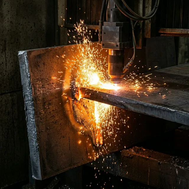
Piercing Techniques for Thick Plate
1. Pulse Piercing (Standard)
Most common method. Uses pulsed power ramping to gradually penetrate material.
Process:
- • Start at 10-20% power, ramp to 100%
- • Pulse duration: 1-5ms
- • Pierce time: 3-15 seconds
- • High gas pressure (15-20 bar)
Pros & Cons:
- OK Safer for optics (less back-reflection)
- OK Cleaner pierce hole
- Slower (3-15 sec per pierce)
2. High-Speed Piercing
Uses full power with controlled oxygen assist. Faster but requires protective measures.
Process:
- • Full power (100%) from start
- • Low O₂ pressure initially (0.5 bar)
- • Ramp gas pressure to 2-3 bar
- • Pierce time: 1-3 seconds
Pros & Cons:
- OK Very fast (1-3 sec)
- OK Higher productivity
- Higher spatter risk
- Requires PierceGate protection
3. Edge Start (Best for Quality)
Start cut from plate edge rather than piercing. Highest quality but limited applicability.
Process:
- • Ramp power from edge (0-100%)
- • Gradual acceleration to cut speed
- • No pierce hole needed
- • Lead-in from outside material
Pros & Cons:
- OK No pierce marks
- OK Highest edge quality
- Requires access to edge
- Not for internal features
Detailed Cutting Parameters
Mild Steel with Oxygen
| Thickness | Power | Speed | O₂ Pressure | Focus | Nozzle |
|---|---|---|---|---|---|
| 20mm | 12kW | 0.6-0.8 m/min | 1.5-2.0 bar | +4mm | 4.0mm |
| 25mm | 15kW | 0.5-0.6 m/min | 1.8-2.2 bar | +5mm | 4.5mm |
| 30mm | 20kW | 0.4-0.5 m/min | 2.0-2.5 bar | +6mm | 5.0mm |
Key Parameter Notes
- Positive Focus: +4 to +8mm above surface for thick plate
- Large Nozzle: 4.0-5.0mm diameter for debris clearance
- Moderate O₂: 1.5-2.5 bar (too high = excessive burning)
- Slow Speed: Quality over speed for thick material
- Beam Quality: M² <1.1 critical for deep penetration
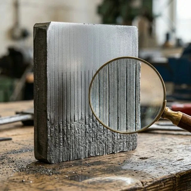
Quality Indicators
- Top Edge: Should be clean, minimal rounding
- Bottom Edge: Slight dross acceptable (<0.5mm)
- Surface Roughness: Ra 12.5-25 μm (ISO 9013 Range 3-4)
- Perpendicularity: ±0.5mm tolerance typical
- Heat Affected Zone: 0.3-0.8mm depth
Common Challenges & Solutions
Challenge: Pierce Hole Blow-Back Damage
Problem: Molten material ejects upward during pierce, damaging optics
Solutions:
- Use PierceGate or protective shutter (Trumpf, Bystronic)
- Start pierce away from edge (>20mm clearance)
- Use pulse piercing instead of full power
- Increase nozzle standoff during pierce (3-5mm)
- Replace protective window every 40-60 hours
Challenge: Excessive Bottom Dross
Problem: Heavy dross formation makes parts unusable without grinding
Solutions:
- Increase cutting speed 10-15%
- Optimize focus position (+0.5 to +1mm adjustment)
- Increase oxygen pressure slightly (0.2-0.3 bar)
- Check material quality (oxide scale causes issues)
- Use larger nozzle (better debris evacuation)
Challenge: Cut Loss (Incomplete Penetration)
Problem: Laser fails to penetrate full thickness
Solutions:
- Increase laser power 15-20%
- Decrease cutting speed 10-15%
- Verify beam quality (M² check)
- Clean/replace focus lens if contaminated
- Check material thickness uniformity (mill scale variation)
Challenge: Taper (Non-Perpendicular Cut)
Problem: Cut angle deviates >1° from perpendicular
Solutions:
- Optimize focus position (critical for thick plate)
- Reduce cutting speed if burning too aggressively
- Check nozzle centering and alignment
- Verify material is flat (max 2mm deviation)
- Consider dual-focus technique (advanced)
Best Practices
Material Preparation
- • Remove heavy mill scale (sand blast if thick)
- • Verify material thickness consistency
- • Check flatness (critical for 20mm+)
- • Use heavy-duty support slats (25mm spacing)
- • Preheat in cold conditions (<10°C)
Process Optimization
- • Start with manufacturer parameters
- • Test cut on scrap (full thickness)
- • Monitor first 3-5 parts closely
- • Document optimal settings by thickness
- • Plan pierce locations away from features
Equipment Requirements
- • Minimum 12kW for 20mm production
- • 20kW+ recommended for 25-40mm range
- • PierceGate or protective shutter essential
- • High-capacity chiller (cooling critical)
- • Robust support structure (heavy plates)
Safety & Maintenance
- • Inspect protective window every 30 hours
- • Monitor cutting head for spatter buildup
- • Clean nozzle exterior daily
- • Replace nozzles every 40-60 hours
- • Heavy debris = fire risk, clean regularly
Cost Considerations for Thick Plate
High Power Requirements
20mm needs 12-15kW, 30mm needs 20-25kW. Equipment cost scales with power.
Slow Cutting Speeds
0.3-0.8 m/min vs 2-5 m/min for thin material. Longer cycle times.
Accelerated Consumable Wear
Nozzles, protective windows wear 2-3× faster due to heavy debris.
Post-Processing Often Required
Grinding bottom dross adds $5-15 per meter of cut.
Typical Cost Impact: Thick plate (20-30mm) costs 3-5× more per part than equivalent 10mm parts due to equipment, time, and consumable requirements.
Data Sources
- • Trumpf High-Power Laser Guide 2024: 15-30kW cutting parameters
- • Bystronic Thick Plate Application Notes: Piercing techniques
- • ISO 9013:2017: Quality classification for thick plate
- • Field data: Structural steel fabrication experience
Disclaimer: Thick plate cutting is challenging and requires high-power equipment (12kW+). Parameters are starting points; optimize based on material condition and quality requirements.