Laser Cutting Terms & Glossary
Master the language of laser cutting technology with our comprehensive glossary covering 30+ essential technical terms and expert FAQ answers. From fundamental concepts like beam quality and kerf width to practical guidance on equipment selection and process optimization—this is your complete reference guide.
How to Use This Glossary: Each term includes a concise definition followed by detailed technical explanation with real-world examples and practical recommendations. Terms are organized by category for easy navigation. Related terms and links to detailed guides are provided for deeper learning.
Fundamental Concepts
Beam Quality (M²)
Measure of how closely the laser beam resembles an ideal Gaussian beam. Lower values (closer to 1.0) indicate better focus capability and precision.
M² (M-squared) quantifies beam divergence and focusability as defined by ISO 11146-1:2021 (Lasers and laser-related equipment - Test methods for laser beam widths, divergence angle and beam propagation ratios). An ideal Gaussian beam has M² = 1.0, while industrial lasers range from 1.05 (premium fiber lasers) to 15+ (high-power CO2 lasers). Lower M² enables: smaller focused spot size (critical for thin materials and fine details), deeper penetration depth for thick materials, and tighter cutting kerf width. Example: M² = 1.1 fiber laser produces 0.05mm spot at 50mm focal length, versus M² = 1.5 CO2 laser producing 0.15mm spot. Trade-off: lower M² lasers typically cost 20-40% more but deliver superior precision. Beam quality degrades over laser lifespan due to optical contamination and thermal effects; monitor via periodic focus testing. | Reference: ISO 11146-1:2021 defines standardized measurement methods for M² parameter.
Depth of Focus (DOF)
Vertical distance range over which the laser beam maintains acceptable focus quality and cutting performance.
DOF determines tolerance to material surface variations, warping, and focus positioning errors. DOF is proportional to focal length and inversely proportional to beam quality: shorter focal length = smaller DOF but higher power density. Typical DOF values: 50mm lens (±0.5mm DOF), 127mm lens (±2mm DOF), 190mm lens (±4mm DOF), 254mm lens (±6mm DOF). Materials with warping or surface irregularities require longer focal lengths to maintain consistent cut quality. DOF decreases with higher power density (tighter focus), making precise focus positioning critical for thin materials. Auto-focus systems maintain optimal focus position automatically, compensating for material warping and ensuring consistent quality.
Focal Length
Distance from the focusing lens to the focal point. Affects depth of focus and cutting capability for different material thicknesses.
Focal length determines spot size, depth of focus (DOF), and working distance. Common focal lengths: 50mm (0.05mm spot, ±0.5mm DOF, thin materials <3mm), 127mm (0.15mm spot, ±2mm DOF, universal standard for 3-15mm), 190mm (0.25mm spot, ±4mm DOF, thick plates 15-25mm), 254mm (0.35mm spot, ±6mm DOF, ultra-thick or 3D cutting). Selection criteria: shorter focal length = higher power density and precision but less tolerance to material warping; longer focal length = more forgiving but larger kerf and lower precision. Lens replacement frequency: 200-1000 operating hours depending on contamination exposure.
Width of material removed by the laser beam. Narrower kerf means less material waste and ability to cut finer details.
Kerf width is the slot width created by laser cutting, as defined in ISO 9013:2017 thermal cutting standards. Typical ranges: 0.05mm (thin materials, low power) to 0.5mm (thick plates, high power). Calculation: kerf ≈ spot diameter + 10-30% (due to melt zone and beam divergence). Material impact: 0.3mm kerf on 1000mm cut removes 300mm² area; on high-value materials (titanium, Inconel), kerf optimization saves significant material cost. Kerf affects: minimum inside corner radius (typically 0.5-1.0x kerf width), small hole capability (hole diameter must be >1.5x material thickness and >kerf width), and nesting efficiency (parts must be spaced >kerf width apart). Kerf compensation: CAD/CAM software offsets cut path by 0.5x kerf width to achieve target dimensions per ISO 9013 tolerance specifications. Fiber lasers produce 20-40% narrower kerf than CO2 lasers due to superior beam quality (M² 1.05-1.15 vs 1.1-1.5). Monitor kerf width via test cuts when changing parameters or materials. | Reference: ISO 9013:2017 defines kerf width measurement and tolerance specifications for thermal cutting.
Energy output of the laser source, measured in watts (W) or kilowatts (kW). Determines maximum material thickness and cutting speed capability.
Power selection depends on material type, thickness range, and production volume. Steel/Stainless: 1kW cuts 0.5-3mm, 3kW cuts 1-8mm (general fabrication, 80% of market), 6kW cuts 3-12mm, 12kW cuts 6-25mm, 20kW+ cuts 10-40mm. Aluminum (harder to cut due to reflectivity): 3kW cuts 1-4mm, 6kW cuts 2-8mm, 12kW cuts 4-15mm. Rule of thumb: choose power where your thickest common material (70% of jobs) falls in the middle of the capability range, not at the extreme limit. Under-powering forces slow speeds and poor quality; over-powering wastes capital but provides future capacity. Power directly affects cutting speed: doubling power typically increases speed by 50-70% (not 100%) due to thermal physics limits.
Material Absorption
Percentage of laser energy absorbed by the material versus reflected or transmitted. Higher absorption enables more efficient cutting.
Absorption varies dramatically with wavelength and material: fiber laser (1064nm) achieves 88-92% on steel/stainless but only 8-15% on aluminum/copper; CO2 laser (10600nm) achieves 90-95% on organics (acrylic, wood) but only 8-10% on metals. Absorption is temperature-dependent: cold aluminum absorbs 8% at 1064nm but increases to 15-25% when heated to 400-600°C, explaining why piercing aluminum is harder than continuous cutting. Material surface condition affects absorption: oxidized steel absorbs better than polished steel, mill scale increases absorption, and coatings can be optimized for laser cutting. Selection principle: choose wavelength with highest absorption for primary material (70%+ of volume). Multi-material shops face trade-offs: fiber laser excels at metals but cannot cut acrylic/wood; CO2 laser handles non-metals but is inefficient on metals.
Spot Size
Diameter of the focused laser beam at the material surface. Smaller spot size enables finer detail cutting and narrower kerf.
Spot size is determined by focal length, beam quality (M²), and beam diameter before focusing. Calculation: spot size ≈ (4 × M² × λ × f) / (π × D), where λ is wavelength, f is focal length, and D is beam diameter. Typical spot sizes: 0.05mm (50mm lens, M²=1.1 fiber laser), 0.15mm (127mm lens, M²=1.5 CO2 laser), 0.25mm (190mm lens). Smaller spot size provides: higher power density (enables cutting or welding), finer detail capability (small holes, tight corners), and narrower kerf (less material waste). Trade-off: smaller spot size has smaller depth of focus, requiring more precise focus positioning. Spot size directly affects kerf width: kerf ≈ spot size + 10-30% (due to melt zone expansion).
Wavelength
The frequency of the laser light, measured in nanometers (nm) or micrometers (μm). Determines which materials the laser can effectively cut through absorption characteristics.
Wavelength determines material absorption efficiency through physics of electron interaction. Common wavelengths: 355nm (UV, 95% absorption on most materials, precision micro-machining), 532nm (green, 55-65% on aluminum/copper, reflective metals), 1064nm (fiber/Nd:YAG, 88-92% on steel/stainless, poor on non-metals), 10600nm (CO2, 90-95% on organics, 8-10% on metals). Selection principle: choose wavelength with highest absorption for primary material (70%+ of volume). Multi-material shops face trade-offs: fiber laser excels at metals but cannot cut acrylic/wood; CO2 laser handles non-metals but is inefficient on metals. Hybrid solution: dual-laser system addresses full material range. Absorption temperature-dependence: cold aluminum absorbs 8% at 1064nm but increases to 15-25% when heated to 400-600°C, explaining why piercing aluminum is harder than continuous cutting.
Process Parameters
Assist Gas
Gas (oxygen, nitrogen, or compressed air) injected through the cutting nozzle to remove molten material and protect optics during laser cutting.
Assist gas serves three critical functions: (1) Expelling molten material from the cut zone through high-pressure injection (typically 0.5-2.0 MPa), (2) Chemically reacting with the material (oxygen creates exothermic reaction for faster cutting of carbon steel), and (3) Protecting the focusing lens from vapor and debris. Gas selection impacts cut quality: oxygen produces oxidized edges at 2-3x faster speeds on mild steel, nitrogen yields oxide-free edges for stainless steel and aluminum but requires 30-50% higher laser power, and compressed air offers economy for thin materials but compromises edge quality. Typical consumption: 0.5-2.0 m³/hr depending on nozzle size and pressure. Cost consideration: nitrogen is 5-10x more expensive than oxygen per m³.
Cutting Speed
Velocity of laser head movement during cutting, measured in meters per minute (m/min) or inches per minute (ipm). Directly impacts productivity and operating cost per part.
Speed ranges by material/thickness: 1mm steel (15-20 m/min fiber, 8-12 CO2), 3mm steel (8-12 fiber, 4-6 CO2), 10mm steel (2-3 fiber, 1-2 CO2), 20mm steel (0.5-1.0 fiber, CO2 impractical). Speed optimization: too fast causes incomplete cutting and excessive dross; too slow causes excessive HAZ and poor edge quality. Optimal speed varies with power: 6kW cuts 3mm steel at 12 m/min vs 3kW at 6-8 m/min (doubling power doesn't double speed due to thermal physics). Speed limiters: material thermal conductivity (aluminum dissipates heat, slowing cutting), assist gas flow rate (insufficient volume limits speed), and machine dynamics (acceleration capability affects small feature cutting). High-speed cutting requires: sufficient laser power reserves, optimized acceleration settings, high-pressure gas delivery (18-25 bar nitrogen), and advanced motion control.
Focus Position
Vertical position of the laser focal point relative to the material surface. Critical parameter affecting cut quality, kerf width, and edge perpendicularity.
Focus position is typically measured from the material surface: positive (above surface, for thin materials to prevent burning), zero (at surface, standard for most applications), or negative (below surface, for thick materials to maximize penetration). Optimal focus varies with material and thickness: thin materials (<3mm) use +0.5 to +1.0mm focus, medium materials (3-10mm) use 0 to -1.0mm, thick materials (>10mm) use -1.0 to -3.0mm. Focus positioning affects: kerf width (wrong focus increases kerf by 20-50%), edge perpendicularity (taper indicates focus error), dross formation (focus position impacts gas flow), and cutting speed (optimal focus enables maximum speed). Auto-focus systems maintain focus position automatically, adjusting for material warping and surface variations.
Nesting
Arrangement of parts on a sheet to maximize material utilization. Good nesting software can significantly reduce waste.
Nesting optimization increases material utilization from 60-75% (manual layout) to 85-95% (advanced algorithms). Techniques: common-line cutting (shares cut paths between adjacent parts, saving 15-25% time and material), true-shape nesting (rotates/mirrors parts for optimal fit), and remnant management (uses off-cuts from previous jobs). Best practices: group parts by material/thickness, respect grain direction for formed parts, maintain 3-5mm edge margin, and allow 1-3mm inter-part spacing. Advanced features: priority nesting (critical parts first), constraint-based layout (orientation limits), and AI-based learning from historical patterns.
Pierce Time
Time required to penetrate material before starting the cut path. Longer for thicker materials; affects overall cycle time.
Pierce time ranges from 0.1 seconds (1mm steel) to 5+ seconds (25mm steel) and directly impacts cycle time on parts with multiple internal features. Optimization strategies: (1) Pulse ramping - gradually increase power to avoid blow-back and lens contamination, (2) Pre-pierce techniques - start at lower power then ramp, reducing time by 20-30%, (3) Edge start - begin cut from sheet edge when possible, eliminating pierce entirely, and (4) Multi-hole piercing - pierce multiple holes before cutting contours, allowing cooling. Advanced systems: dynamic piercing adjusts parameters based on material thickness and type. Pierce failure indicators: excessive spatter, lens damage, or incomplete penetration.
Equipment & Technology
CNC (Computer Numerical Control)
Automated control system that operates the laser cutter via pre-programmed sequences, translating CAD designs into precise cutting paths.
Modern laser CNCs integrate: motion control (servo/stepper motors driving X-Y-Z axes), process control (laser power modulation, gas flow), I/O management (sensors, limit switches, emergency stops), and HMI (human-machine interface). Leading controller brands: Siemens (Sinumerik, excellent dynamics), Fanuc (proven reliability), Beckhoff (open architecture), and domestic brands (cost-effective for basic applications). Performance metrics: positioning accuracy (±0.02mm high-end vs ±0.10mm entry-level), max traversing speed (80-120 m/min), acceleration (1.0-2.5G), and interpolation capability (5-axis simultaneous for tube cutting). Software ecosystem: controllers run on Windows or Linux, interface via Ethernet/SERCOS/EtherCAT, and support industry protocols (G-code, ESSI, proprietary formats).
Laser using electrically-excited CO2 gas mixture as gain medium, producing 10.6μm wavelength. Ideal for non-metallic materials (wood, acrylic, fabric) due to excellent absorption.
CO2 laser characteristics: 10600nm wavelength (10x longer than fiber), 10-15% wall-plug efficiency, M² = 1.1-1.5 (excellent beam quality), and 2,000-10,000 hour tube life (RF-excited) or 10,000-20,000 hours (DC-excited). Power ranges: 20-150W (engraving, thin non-metals), 150-500W (signage, thicker acrylic/wood), 500-2000W (industrial cutting), 2-6kW (metal cutting, becoming obsolete vs fiber). Material absorption: 90-95% on organics (acrylic, wood, leather, fabric), 50-70% on ceramics/glass, but only 8-10% on metals (making metal cutting inefficient). Applications: signage (flame-polished acrylic edges, no post-processing), architectural models, textile cutting (fashion industry), and packaging prototypes. Maintenance: mirror cleaning/alignment every 200-500 hours, tube replacement every 2,000-10,000 hours.
Duty Cycle
Percentage of time a laser can operate at full power without overheating. Higher duty cycle means more continuous operation capability.
Duty cycle reflects thermal management capacity. Consumer lasers: 20-50% (cut 20 minutes, cool 40 minutes per hour). Industrial lasers: 80-100% (continuous operation with minor deratings). Factors affecting duty cycle: ambient temperature (30°C vs 40°C can reduce duty by 15%), chiller capacity (under-spec chillers throttle power), and material type (reflective aluminum generates more heat than steel). Real-world impact: 50% duty cycle system requires 2x as much calendar time for same production volume. Fiber lasers typically achieve 95-100% duty cycle due to superior thermal design, while older CO2 lasers range 70-90%. Verify duty cycle at maximum power and worst-case ambient conditions before purchase.
Fiber Laser
Laser type using optical fiber doped with rare-earth elements (ytterbium, erbium) as gain medium. Dominant technology for metal cutting due to high efficiency, low maintenance, and excellent beam quality.
Fiber laser advantages: 25-30% wall-plug efficiency (vs 10-15% CO2), M² = 1.05-1.15 (excellent focusability), maintenance-free design (no beam path alignment, no consumable optics), compact footprint (1/3 size of equivalent CO2), and 100,000+ hour lifespan. Power ranges: 500W-1kW (thin sheet, electronics), 1-3kW (general fabrication, 0.5-8mm steel), 3-6kW (medium plate, 1-12mm), 6-12kW (thick plate, 3-20mm), 12-30kW (ultra-thick, shipbuilding, heavy industry). Wavelength 1064nm provides 88-92% absorption on steel/stainless but only 8-15% on aluminum/copper (requiring high power for reflective metals). Operating costs: $3-8/hour all-in (electricity, consumables, maintenance). Market leaders: IPG Photonics, Trumpf, Raycus, and nLIGHT. Technology trends: beam shaping (variable spot size for quality optimization), wobble cutting (circular beam motion for smoother edges), and ultra-high power (40-60kW for shipbuilding).
Nozzle
Consumable component that directs assist gas flow onto the cut zone. Nozzle size and condition significantly affect cut quality.
Nozzle types: standard (1.0-2.5mm diameter, general cutting), conical (for thick materials, better gas flow), and specialized (for specific applications). Nozzle diameter selection: smaller nozzle (1.0-1.5mm) provides higher gas velocity and better edge quality for thin materials but requires more frequent replacement; larger nozzle (2.0-2.5mm) offers longer life and better performance on thick materials. Nozzle standoff distance: typically 0.5-2.0mm from material surface, adjusted based on material thickness and cutting speed. Nozzle wear indicators: visible damage, increased dross, reduced edge quality, or inconsistent gas flow. Replacement frequency: every 8-40 hours of cutting depending on material and power level. Cost: $15-80 per nozzle. Proper nozzle maintenance extends life: regular cleaning, avoiding collisions, and using appropriate size for application.
Quality Metrics
Solidified molten material that adheres to the bottom edge of a cut. Excessive dross indicates suboptimal cutting parameters or worn consumables.
Dross formation mechanisms: insufficient assist gas pressure (molten material not fully expelled), too-slow cutting speed (excessive heat input), incorrect focus position (beam geometry mismatch), or worn nozzle (disrupted gas flow). Dross types: (1) Top-side dross (rare, indicates severe parameter error), (2) Bottom-side adherent dross (common, removable by grinding but adds labor), and (3) Solidified beads (worst case, requires cutting re-work). Acceptance criteria: Class 1 parts (aerospace, medical) allow zero dross; Class 2 (automotive) tolerates light removable dross; Class 3 (general fabrication) permits moderate dross. Removal methods: hand grinding (5-15 minutes/part), vibratory finishing (batch process, 30-60 minutes), or chemical dissolution (for aluminum). Prevention: increase assist pressure +10-20%, increase cutting speed +5-10%, verify nozzle condition, and optimize focus position (typically 0.5-1.5mm into material).
Surface finish of the cut edge, characterized by roughness (Ra), perpendicularity, dross, and HAZ. Higher quality grades command premium pricing in aerospace and medical applications.
Edge quality is classified by ISO 9013:2017 (Thermal cutting - Classification of thermal cuts - Geometrical product specification and quality tolerances) into quality ranges: Range 1 (Ra <3.2μm, perpendicularity <0.05mm, precision applications), Range 2 (Ra 3.2-6.3μm, perpendicularity 0.05-0.15mm, general fabrication), Range 3 (Ra 6.3-12.5μm, perpendicularity 0.15-0.30mm, rough cutting), Range 4 (Ra >12.5μm, demolition/scrap). Measurement: surface roughness tester (portable units available) or visual comparison charts per ISO 9013 standards. Edge quality drivers: cutting speed (faster = rougher within optimal window), laser power stability (±2% fluctuation degrades quality), material quality (mill scale and impurities create irregularities), and consumable condition (worn nozzles reduce quality by 1-2 grades). Troubleshooting: striations indicate speed/power mismatch, excessive taper suggests focus error, and bottom-edge roughness points to insufficient assist gas. Fiber lasers typically achieve 1 grade better edge quality than CO2 lasers at equivalent speeds due to superior beam quality and absorption. | Reference: ISO 9013:2017 provides standardized classification and measurement methods for thermal cut quality.
HAZ (Heat Affected Zone)
Area of base material whose properties have been changed by the heat of cutting. Smaller HAZ indicates cleaner, more precise cutting.
Heat Affected Zone (HAZ) is defined in ISO 9013:2017 as the region adjacent to the thermal cut where material properties are altered by heat. HAZ extends 0.1-2.0mm beyond the cut edge depending on laser power, cutting speed, and material thermal conductivity. Within HAZ: grain structure changes, hardness variation (±50-200 HV), residual stress accumulation, and potential micro-cracking. Minimizing HAZ: increase cutting speed (reduces heat input time), use nitrogen instead of oxygen (eliminates exothermic reaction), optimize focus position (concentrate energy), and employ pulsed mode for heat-sensitive materials. Industry standards: aerospace/medical applications require HAZ <0.2mm; general fabrication tolerates 0.5-1.0mm. Measurement: metallographic cross-section analysis per ISO 9013 or hardness testing. Materials highly sensitive to HAZ: spring steel, tool steel, heat-treated alloys. Fiber lasers produce 30-50% smaller HAZ than CO2 lasers at equivalent cut quality due to higher absorption and faster speeds. | Reference: ISO 9013:2017 defines HAZ measurement and classification for thermal cutting processes.
Positioning Accuracy
Ability of the machine to move the laser head to the commanded position. Measured as deviation from target position.
Positioning accuracy is critical for precision applications and multi-pass operations. Typical values: ±0.02mm (high-end systems), ±0.05mm (mid-range), ±0.10mm (entry-level). Factors affecting accuracy: servo motor quality, mechanical backlash, thermal expansion, and control system precision. Repeatability (ability to return to same position) is typically 2-3x better than accuracy. Accuracy requirements vary by application: sheet metal fabrication (±0.05mm acceptable), precision parts (±0.02mm required), micro-machining (±0.005mm needed). Regular calibration maintains accuracy: ballbar testing, laser interferometry, or grid plate measurement. Environmental factors: temperature variations, foundation stability, and vibration affect long-term accuracy.
Surface Roughness (Ra)
Measure of the texture of the cut edge surface, expressed as arithmetic average deviation from mean line. Lower Ra values indicate smoother edges.
Ra values are measured in micrometers (μm). ISO 9013 classifications: Range 1 (Ra <3.2μm, precision applications), Range 2 (Ra 3.2-6.3μm, general fabrication), Range 3 (Ra 6.3-12.5μm, rough cutting), Range 4 (Ra >12.5μm, demolition/scrap). Factors affecting surface roughness: cutting speed (optimal speed produces smoothest edge), laser power stability (±2% fluctuation degrades quality), material quality (mill scale and impurities create irregularities), assist gas pressure (insufficient pressure increases roughness), and consumable condition (worn nozzles reduce quality). Measurement: portable surface roughness tester or visual comparison charts. Edge roughness affects: post-processing requirements (smoother edges need less finishing), fit-up quality (mating surfaces), and appearance (visible edges).
Quick Reference Tables
Fiber Laser vs CO2 Laser Comparison
| Parameter | Fiber Laser | CO2 Laser |
|---|---|---|
| Wavelength | 1064 nm | 10600 nm |
| Beam Quality (M²) | 1.05-1.15 | 1.1-1.5 |
| Efficiency | 25-30% | 10-15% |
| Steel Absorption | 88-92% | 8-10% |
| Lifespan | 100,000+ hours | 2,000-20,000 hours |
| Best For | Metals (steel, stainless, aluminum) | Non-metals (acrylic, wood, fabric) |
Focal Length Selection Guide
| Focal Length | Spot Size | DOF | Best For |
|---|---|---|---|
| 50 mm | ~0.05 mm | ±0.5 mm | Thin materials <3 mm |
| 127 mm | ~0.15 mm | ±2 mm | Universal 3-15 mm |
| 190 mm | ~0.25 mm | ±4 mm | Thick plates 15-25 mm |
| 254 mm | ~0.35 mm | ±6 mm | Ultra-thick or 3D cutting |
Laser Power Selection by Material Thickness
| Laser Power | Steel/Stainless | Aluminum | Applications |
|---|---|---|---|
| 1 kW | 0.5-3 mm | 0.5-2 mm | Thin sheet, electronics |
| 3 kW | 1-8 mm | 1-4 mm | General fabrication |
| 6 kW | 3-12 mm | 2-8 mm | Medium plate |
| 12 kW | 6-25 mm | 4-15 mm | Thick plate, structural |
| 20+ kW | 10-40 mm | 8-25 mm | Shipbuilding, heavy industry |
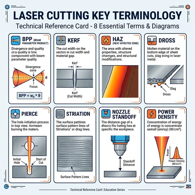
Visual Reference Diagrams
Kerf Width Illustration
Focus Position & Depth of Focus
Focus position is measured relative to the material surface. Optimal focus varies by material thickness and cutting parameters.

Frequently Asked Questions
Laser power (measured in kW) is the energy output of the laser source. Higher power enables cutting thicker materials and achieving faster speeds on any given thickness. Cutting speed is how fast the laser head physically moves while cutting, measured in meters per minute (m/min). The relationship is not linear: doubling power typically increases speed by 50-70% (not 100%) due to thermal physics limits on how quickly material can absorb and melt. Optimal cutting speed balances productivity (faster = more parts/hour) with quality (too fast causes dross and incomplete cuts; too slow creates excessive HAZ and rough edges).
Related Resources
Unit Reference
Power & Energy
- kW = kilowatt (1,000 watts)
- W = watt
- J = joule (energy unit)
Distance & Size
- mm = millimeter (1/1000 meter)
- μm = micrometer (1/1000 mm)
- nm = nanometer (1/1000 μm)
Speed & Rate
- m/min = meters per minute
- ipm = inches per minute
- m³/hr = cubic meters per hour