Need help applying this guide to a real purchase or process setup?
Send your material, thickness, machine power, budget, or supplier question. We can help translate the guide into practical next steps.
By LaserSpecHub Engineering Team
Content reviewed and updated March 2026
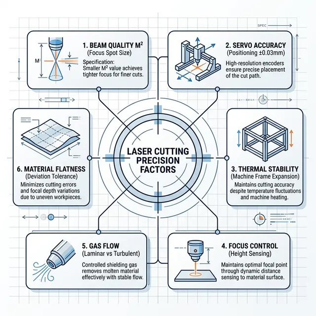
Laser Cutting Precision Factors Comparison
Six critical factors affecting laser cutting precision
Understanding the engineering principles and trade-offs that determine whether a laser cutting system can achieve ±0.01mm, ±0.05mm, or ±0.1mm positioning accuracy in production environments.
Engineering Deep Dive5 Critical FactorsReal-world Data2500+ Words
Precision Claim Validation Path
Treat advertised positioning accuracy as a machine-axis claim, not a finished-part tolerance guarantee. Validate repeatability with a cut coupon, then separate motion error, kerf compensation, thermal drift, material flatness, and beam/focus stability before approving a precision job.
Laser cutting precision is not a single specification—it's the cumulative result of five interacting subsystems. While manufacturers often advertise positioning accuracy of ±0.03mm or better, achieving this consistently in production requires understanding and managing all five factors:
Mechanical Structure (40% impact)
Gantry rigidity, linear guide quality, and structural resonance determine the physical limits of positioning accuracy. Premium machines use welded steel frames, ground ball screws, and granite beds to minimize deflection.
Servo & Control System (25% impact)
Closed-loop servo motors with encoder feedback, combined with advanced CNC algorithms (look-ahead, jerk control), enable smooth acceleration and sub-micron positioning resolution.
Beam Quality & Optics (20% impact)
Beam quality (M² factor), focal spot size, and optical alignment directly affect the effective cutting width and edge straightness. Poor beam quality can negate mechanical precision.
Thermal Stability (10% impact)
Temperature changes cause frame expansion, guide rail deformation, and focal length drift. Climate-controlled facilities and thermal compensation are critical for ±0.01mm accuracy.
Software Algorithms (5% impact)
Path optimization, contour smoothing, and error compensation in the CNC software can improve effective accuracy by 10-20% through intelligent motion planning.
Understanding Precision Terminology
Key Definitions: Positioning vs. Repeat Accuracy
Positioning Accuracy
The maximum deviation between the commanded position and the actual positionreached by the cutting head. This measures systematic errors in the machine's ability to move to a specific coordinate.
Example: If the CNC commands X=1000.00mm and the head stops at X=1000.03mm, the positioning error is 0.03mm.
Positioning accuracy affects absolute dimensional accuracy (can parts be assembled?).Repeatability affects part-to-part consistency (will 100 identical parts match?). For production, repeatability is often more critical because systematic errors can be compensated through software calibration, but random variations cannot.
The mechanical foundation is the single most important factor in laser cutting precision. No amount of sophisticated software or servo tuning can compensate for a flexing gantry or worn linear guides. Premium machines invest heavily in structural engineering to achieve micron-level rigidity.
Frame Construction Materials
Welded Steel Frame (Standard)
Most machines use 8-12mm thick steel plate welded into a box structure. After welding, frames undergo stress-relief annealing (600-650°C) to remove internal stresses that cause warping over time.
Precision: ±0.03-0.05mm | Cost: Moderate | Stability: Good
Cast Iron Bed (Premium)
European machines (TRUMPF, Bystronic) often use cast iron beds similar to CNC machining centers. Cast iron has excellent vibration damping (5× better than steel) and dimensional stability.
Precision: ±0.01-0.02mm | Cost: High | Stability: Excellent
Granite + Steel Hybrid (Ultra-Premium)
Some ultra-precision machines use granite slabs (natural stone) as the base, combined with steel gantries. Granite has near-zero thermal expansion and superb flatness (±0.005mm over 3 meters).
Precision: ±0.01mm | Cost: Very High | Stability: Outstanding
Linear Motion Systems
Profile Rail Guides (Budget)
Square or rectangular rail guides with sliding blocks. Lower cost but prone to wear and backlash. Typical lifespan: 2-3 years in production. Common in Chinese budget machines.
Ground steel rails with recirculating ball bearing blocks (THK, HIWIN, PMI brands). Low friction, high precision, long life. The industry standard for mid-to-high-end machines.
Heavy-duty roller guides or oil-film hydrostatic bearings for ultra-high loads and precision. Used in machines cutting thick plates (20mm+) where rigidity is paramount.
Ground ball screws (C3 or C5 grade) convert rotary motion to linear motion with minimal backlash. Precision-grade screws are ground to ±0.005mm/300mm and pre-loaded to eliminate play. Maximum practical length: 3-4 meters due to critical speed limits and thermal expansion.
Advantages:
Excellent positioning accuracy (±0.01-0.03mm)
High repeatability (±0.005-0.01mm)
No backlash with preload
Long lifespan (30,000-50,000 hours)
Limitations:
Maximum speed: 60-100 m/min
Length limited to ~4m (critical speed)
Thermal expansion affects long screws
Higher cost than rack systems
Rack & Pinion Drive (High Speed, Large Format)
Ground racks (teeth machined to ±0.01mm pitch accuracy) driven by helical pinion gears. Enables higher speeds (150+ m/min) and unlimited length for large-format machines (6m+ beds). Requires dual-pinion preload to minimize backlash.
Advantages:
High speed (150-200 m/min rapids)
Unlimited length (modular racks)
Good for large-format machines (6m+)
Lower cost for long axes
Limitations:
Lower precision (±0.05-0.08mm typical)
Backlash requires compensation
Rack wear over time
Pitch errors between rack segments
Engineering Insight: Gantry Deflection
A 3-meter steel gantry beam weighing 200kg will deflect approximately 0.15mm in the center under its own weight without proper support. Premium machines use:
Box-section beams (200mm × 150mm × 10mm wall) for 4× higher stiffness than I-beams
Dual-drive systems (motors on both ends) to eliminate torsional twist
Active deflection compensation in CNC software (Z-axis micro-adjustment based on X position)
For businesses requiring consistent precision across the entire work envelope, manufacturers likeOPMT Laser employ finite element analysis (FEA) to optimize gantry profiles and minimize deflection to below 0.02mm, ensuring that advertised precision specs hold true across the full cutting area, not just at calibration points.
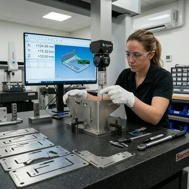
Precision verification with a Hexagon CMM: dimensional readings to ±0.01mm confirm that mechanical structure, servo tuning, and optical alignment are working harmoniously.
Factor 2: Servo & Control Systems (25% Impact)
The servo and CNC control system translates G-code commands into precise motor movements. Advanced servo algorithms, encoder resolution, and control loop frequency determine how accurately the mechanical system tracks the commanded path.
Servo Motor & Encoder Resolution
Stepper Motors (Budget Machines)
Open-loop control with 200-400 steps/revolution. No position feedback, prone to lost steps under high acceleration or load. Positioning error accumulates over time.
Typical Accuracy: ±0.1-0.2mm | Repeatability: ±0.05-0.1mm |Max Speed: 60 m/min | Used in: Entry-level CO2 engravers, budget fiber lasers
AC Servo Motors with Incremental Encoders (Standard)
Closed-loop control with 2500-5000 pulse/revolution encoders (typical resolution: 0.002-0.005mm after ball screw gearing). Position feedback enables error correction and high dynamic performance.
Direct position measurement via linear optical scales (0.001mm resolution) mounted on the machine bed. Eliminates cumulative error from ball screw pitch variation and thermal expansion. Used in ultra-precision machines.
Loop Frequency determines how often the control system updates motor commands. Higher frequency (8-16 kHz) enables smoother contours and better tracking accuracy on complex curves. Look-ahead allows the CNC to pre-analyze upcoming G-code blocks and optimize acceleration/deceleration, reducing corner rounding and overshoot.
Real-World Impact: Corner Accuracy
When cutting a 90° corner at 3000 mm/min, the machine must decelerate from full speed to nearly zero, change direction, and re-accelerate—all within 2-3mm of travel. The challenges:
Low-end systems: Abrupt stop/start causes corner rounding (0.3-0.5mm radius), vibration, and potential servo following error alarms.
Mid-range systems: S-curve acceleration smooths motion but still produces 0.1-0.2mm rounding.
Premium systems: Jerk-limited motion planning + look-ahead maintains ≤0.05mm corner radius while optimizing speed for maximum throughput.
This is why dynamic precision (accuracy while cutting) often differs from static precision(accuracy during slow positioning moves). Manufacturers likeOPMT Laserperform extensive servo tuning and motion profiling to ensure that advertised precision holds even during high-speed cutting operations.
Factor 3: Beam Quality & Optical System (20% Impact)
Even with perfect mechanical positioning, poor beam quality or misaligned optics will result in inconsistent cut edges and dimensional errors. The laser beam's characteristics—spot size, M² factor, and focal stability— directly determine the effective cutting precision.
Beam Quality (M² Factor) and Focal Spot Size
Understanding M² (Beam Quality Factor)
M² (M-squared) describes how close a laser beam is to an ideal Gaussian beam (M² = 1.0). Lower M² = smaller focal spot = higher power density = better precision. For fiber lasers:
Single-Mode (M² < 1.5)
Spot size: 0.05-0.08mm | Ideal for thin sheets (≤3mm) requiring tight tolerances and minimal HAZ.
Best for: Precision electronics, fine art cutting
Multi-Mode Standard (M² 1.8-2.2)
Spot size: 0.1-0.15mm | Balanced performance for general sheet metal (1-12mm). Most common in production machines.
Best for: General fabrication, automotive parts
High-Power Multi-Mode (M² > 2.5)
Spot size: 0.2-0.3mm | Larger spot distributes power for thick plate cutting (≥20mm). Lower precision.
Best for: Heavy fabrication, thick plate (20-40mm)
Focal Spot Size Impact on Kerf Width
The kerf width (cutting gap) is approximately 1.2-1.5× the focal spot diameter plus material-dependent melt expansion. This directly affects achievable part accuracy:
Example: 100mm square hole
Design size: 100.00mm
Kerf width 0.15mm → Actual: 99.925mm
Kerf width 0.25mm → Actual: 99.875mm
Conclusion: 0.1mm variation in kerf = 0.05mm error in final dimension
Kerf Compensation Strategies
CAM software kerf offset (most common)
Test cut calibration on scrap material
Adaptive power/speed for consistent kerf
Real-time kerf monitoring (premium systems)
Optical Alignment & Focal Length Stability
Common Optical Misalignment Issues
Beam Offset from Nozzle Center
If the laser beam doesn't pass through the exact center of the nozzle (coaxial misalignment), the effective cut position shifts by 0.05-0.15mm depending on the offset. This causes:
Tapered cut edges (top/bottom offset)
Direction-dependent dimensional errors
Uneven kerf width on different cut sides
Focus Position Drift
Thermal expansion of the cutting head and lens holder can cause the focal point to shift ±0.5-1.0mm during a production run. This affects:
Cutting quality degradation after 30-60 minutes
Inconsistent kerf width (first vs. last part)
Requires warm-up time for stable performance
Premium Solutions for Optical Stability
OKWater-cooled cutting heads: Maintain lens temperature within ±2°C, preventing focal drift
OKAutomatic beam alignment systems: Laser-based centering checks and auto-corrects coaxiality before each job
OKCollimation stability monitoring: Detects beam divergence changes and alerts operator for optics cleaning/replacement
Factor 4: Thermal Stability & Environmental Control (10% Impact)
Temperature variations cause predictable dimensional changes in machine structures, linear guides, and ball screws. For ultra-precision applications (±0.01mm), thermal management is non-negotiable.
Thermal Expansion Effects on Precision
Linear Thermal Expansion Coefficients
Material
Coefficient (μm/m·°C)
3m Frame @ 10°C Change
Notes
Steel
11-13
0.33-0.39mm
Most common frame material
Aluminum
23-24
0.69-0.72mm
Avoid for precision machines
Cast Iron
10-11
0.30-0.33mm
Better thermal stability
Granite
3-8
0.09-0.24mm
Ultra-precision applications
Invar (Nickel Alloy)
1-2
0.03-0.06mm
Extremely expensive, rarely used
Conclusion: A 10°C temperature swing (e.g., morning 15°C to afternoon 25°C) causes a 3-meter steel frame to expand by 0.36mm—12× larger than ±0.03mm positioning accuracy!
Environmental Requirements by Precision Class
Economy Precision (±0.1mm)
No special climate control required. Can operate in typical factory environment (10-35°C variation).
Standard Precision (±0.05mm)
Basic climate control recommended: 15-30°C, ±5°C variation max. Warm-up period 30-60 minutes.
High Precision (±0.02-0.03mm)
Climate-controlled facility: 20-24°C, ±2°C variation. HVAC system with ±0.5°C regulation. Machine warm-up 2-3 hours before precision work.
Ultra-Precision (±0.01mm)
Metrology-grade environment: 20°C ±0.5°C, humidity 50% ±5%, isolated from external vibration. Thermal compensation software + foundation isolation required.
Case Study: Thermal Drift in Production
Scenario: A fabrication shop with a mid-range 6kW fiber laser (±0.03mm spec) operating in an un-climate-controlled facility experiences the following:
Morning (7 AM, 16°C): Parts cut 0.08mm undersized due to cold machine. Operator adjusts offset.
Afternoon (2 PM, 28°C): Temperature rise of 12°C causes frame expansion. Same program now cuts parts 0.05mm oversized. Previous offset compensation is now incorrect.
Evening (6 PM, 24°C): Cooling phase causes another dimensional shift. 30% of parts require rework.
Solution: Installing a basic HVAC system (20-25°C ±2°C) reduced thermal drift to <0.02mm, cutting rework from 30% to 3%. ROI: 8 months from reduced scrap.
Modern CNC software includes sophisticated algorithms to compensate for mechanical imperfections and optimize motion trajectories. While hardware provides the foundation, intelligent software can improve effective accuracy by 10-20%.
Key Software Features for Precision Enhancement
Backlash Compensation
Compensates for mechanical play in drive systems (rack & pinion, gearboxes). Software adds a small overshoot when reversing direction to "take up" backlash before reaching the target position. Typical compensation: 0.01-0.05mm per axis.
Leadscrew Pitch Error Mapping
Ball screws have microscopic pitch variations (±5μm/300mm even in precision-grade screws). Advanced CNCs measure actual position at 50-100 points along each axis using a laser interferometer, then apply corrections during motion. Improves accuracy by 30-50%.
Thermal Expansion Compensation
Temperature sensors (5-10 points on frame and axes) feed data to the CNC, which applies real-time position corrections based on thermal expansion models. Can reduce thermal drift error by 70-80%. Common in European premium machines.
Look-Ahead Path Optimization
The CNC pre-analyzes 200-1000 upcoming G-code blocks to optimize speed, acceleration, and corner smoothing. Prevents abrupt stops that cause vibration and overshoot. Essential for complex contours and nested parts.
Kerf Width Auto-Calibration
Some premium systems use vision systems or edge detection sensors to measure actual kerf width during test cuts, then automatically adjust CAM offsets for that specific material/thickness/power combination. Eliminates manual trial-and-error.
Software Comparison: Impact on Effective Precision
CNC Software
Compensation Features
Mechanical Precision
Effective Precision
Improvement
Basic (RDWorks)
None
±0.1mm
±0.1mm
0%
Mid-Range (Cypcut)
Backlash, basic look-ahead
±0.05mm
±0.04mm
20% better
Premium (Beckhoff)
Full compensation suite
±0.03mm
±0.02mm
33% better
Ultra (Siemens 840D)
All + thermal + vision
±0.02mm
±0.012mm
40% better
Practical Selection Guide: Matching Precision to Application
When Do You Actually Need ±0.01mm Precision?
Many buyers over-specify precision requirements, paying 2-3× more for capabilities they don't need. Here's a realistic assessment:
You DON'T Need Ultra-Precision (±0.01mm) If:
Parts are welded/assembled (welding distortion: 0.5-2mm)
Key Insight: The cost premium for ultra-precision is 3-4× vs. standard precision, but the scrap reduction in high-volume production often justifies it within 12-18 months.
Key Takeaways
1.Precision is a system property, not a single component. Achieving ±0.02mm requires excellence in mechanical structure, servo control, beam quality, thermal management, and software—simultaneously.
2.Mechanical structure accounts for 40% of precision performance. Gantry rigidity, linear guide quality, and ball screw accuracy set the physical limits that no amount of software can overcome.
3.Dynamic precision differs from static precision. A machine may achieve ±0.01mm in slow positioning but only ±0.05mm during high-speed cutting due to servo following errors and vibration.
4.Thermal stability is critical for sustained accuracy. A 10°C temperature change can cause 0.3mm+ dimensional shift in a 3-meter machine—10× larger than advertised precision specs.
5.Specify precision based on actual requirements, not aspirations. Ultra-precision machines cost 3-4× more but are only justified for close-tolerance assemblies, miniature parts, or high-volume production where scrap cost exceeds machine premium within 12-18 months.