
โก Quick Reference
6mm Mild Steel (6kW Fiber): 3.0-4.0 m/min |3mm Stainless: 8-12 m/min |10mm Aluminum: 1.5-2.5 m/min |6mm Steel (CO2 4kW): 2.0-2.8 m/min
Comprehensive cutting speed data for fiber and CO2 lasers across various materials and thicknesses. Use this reference to estimate production times and optimize your cutting parameters.
Note: These are typical speeds under optimal conditions. Your actual speeds may vary based on equipment condition, material quality, and specific cutting requirements.

Visual representations of how power, thickness, materials, and gas types affect cutting speeds
Mild Steel - 10mm thickness (Diminishing returns at higher power)
3kW Fiber Laser - Mild Steel (Logarithmic relationship)
6kW laser power - 5mm thickness
Mild Steel - 3kW Fiber Laser (Oxygen vs Nitrogen)
Speed adjustments from baseline (Standard = 10 m/min)
Note: Higher quality requires slower speeds to achieve better edge finish, tighter tolerances, and minimal dross. Choose based on your application requirements.
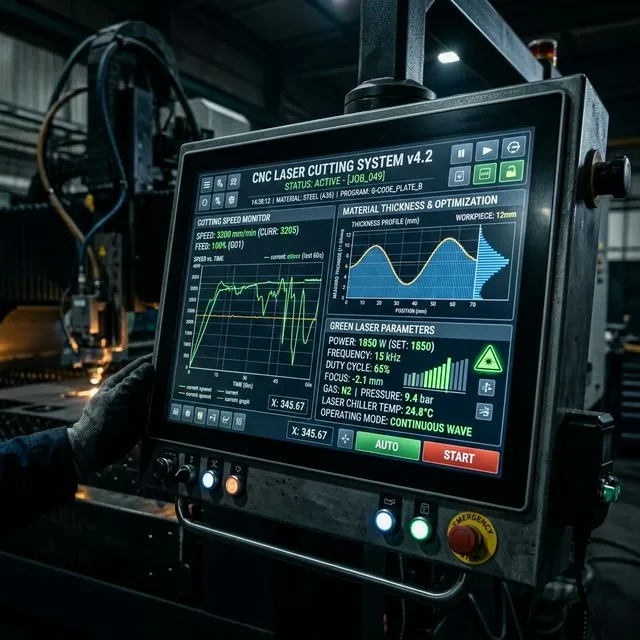
Cutting speed is perhaps the most visible performance metric in laser cutting, directly impacting production throughput and operational costs. However, the relationship between laser power, material properties, and achievable cutting speed is complex and non-linear. Understanding these dynamics enables better equipment selection and process optimization.
Laser cutting speed is fundamentally limited by the rate at which material can be heated to melting/vaporization temperature and ejected from the kerf. This involves three simultaneous processes: energy absorption, heat conduction into surrounding material, and melt ejection via assist gas. The balance between these processes determines maximum achievable speed.
For thin materials (0.5-3mm), heat conduction is the limiting factor. Energy quickly dissipates laterally, requiring high power density (small focus spot) and fast traverse to maintain cutting. This is why fiber lasers with excellent beam quality (Mยฒ < 1.2) excel at thin sheet cutting, achieving speeds of 20-40 m/min on 1mm steel with just 2-3kW power.
For thick materials (12mm+), melt ejection becomes the bottleneck. Even with sufficient power to melt material, assist gas must physically remove molten metal through the entire thickness. This requires high gas pressure (15-20 bar for nitrogen) and larger nozzles, but ultimately limits speed regardless of available power. A 12kW laser cutting 20mm steel typically maxes out at 1.5-2.0 m/min, not due to power limitations but melt dynamics.
Different materials exhibit dramatically different cutting speed profiles. Carbon steel benefits from oxygen-assist cutting, where the exothermic reaction between oxygen and iron contributes 30-40% of total cutting energy. This allows speeds 40-60% faster than nitrogen cutting. For example, 3kW cutting 6mm mild steel: oxygen achieves 3.5 m/min versus nitrogen at 2.2 m/min.
Stainless steel's low thermal conductivity means heat stays concentrated in the cutting zone, theoretically beneficial for cutting. However, its high reflectivity at 1.06ฮผm (fiber laser wavelength) and tendency to oxidize require nitrogen assist, reducing speeds 20-30% compared to carbon steel of equivalent thickness. The quality-speed tradeoff is particularly pronounced: achieving mirror-finish edges on stainless requires reducing speed by an additional 25-30% below standard production speeds.
Aluminum presents the greatest challenge for fiber lasers due to extreme reflectivity (>90% at 1.06ฮผm) and high thermal conductivity. Successful aluminum cutting requires 30-50% more power than equivalent steel thickness. Modern fiber lasers with specialized aluminum cutting modes employ dynamic power modulation and optimized beam characteristics to improve aluminum absorption, achieving speeds approaching 70-80% of steel cutting rates rather than the traditional 50-60%. Learn more about material absorption characteristics.
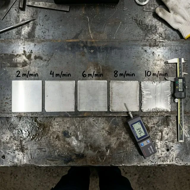
A common misconception is that doubling laser power doubles cutting speed. In reality, the relationship follows a power law with diminishing returns. For thin materials (1-3mm), doubling power increases speed by approximately 60-80%. For medium thickness (6-10mm), the increase drops to 40-60%. For thick materials (15mm+), doubling power may only increase speed by 20-30%.
This non-linearity stems from heat dissipation dynamics. At higher speeds, less time is available for heat to conduct into surrounding material, requiring disproportionately more power to maintain cutting temperature. Additionally, assist gas dynamics become limiting - there's a maximum rate at which molten material can be ejected regardless of available power.
The practical implication: upgrading from 3kW to 6kW provides substantial speed gains (50-70% faster on 6-8mm steel). However, upgrading from 12kW to 20kW yields modest improvements (15-25% faster on 20mm steel), making the investment harder to justify purely on speed grounds. The higher power is better justified for capability (cutting thicker materials) rather than speed on existing thicknesses.
The speeds shown in reference tables represent standard production quality - smooth edges with minimal dross, acceptable for most fabrication applications. However, different applications demand different quality levels, requiring speed adjustments:
The cutting speeds in reference tables assume optimal conditions: clean material, proper focus, fresh nozzles, optimal gas pressure, and stable power output. Real-world conditions introduce variability that affects achievable speeds:
Material surface condition significantly impacts speed. Mill scale, rust, or oil on steel surfaces can reduce effective cutting speed by 10-20%. Pre-painted or galvanized materials require 15-25% speed reduction to avoid burning coatings beyond the cut edge. Material flatness matters too - warped sheets require slower speeds to maintain consistent focus distance, or risk incomplete cuts.
Equipment condition is critical. Worn nozzles reduce gas flow efficiency, requiring 5-10% speed reduction. Contaminated optics reduce delivered power, effectively operating as if with lower power. Focus drift due to thermal effects in continuous operation can reduce effective cutting speed by 10-15% after several hours of operation without recalibration. See our process optimization guide for maintenance best practices.
High-efficiency metal cutting - Best for steel, stainless steel, aluminum
| Thickness (mm) | 1kW | 2kW | 3kW | 4kW | 6kW | 8kW | 12kW | 15kW | 20kW |
|---|---|---|---|---|---|---|---|---|---|
| 1mm | 15 m/min | 25 m/min | 35 m/min | 45 m/min | 60 m/min | 75 m/min | 90 m/min | โ | โ |
| 2mm | 8 m/min | 14 m/min | 20 m/min | 26 m/min | 35 m/min | 45 m/min | 60 m/min | โ | โ |
| 3mm | 4 m/min | 7 m/min | 10 m/min | 14 m/min | 20 m/min | 26 m/min | 38 m/min | โ | โ |
| 5mm | 2 m/min | 3.5 m/min | 5 m/min | 7 m/min | 10 m/min | 13 m/min | 20 m/min | โ | โ |
| 8mm | 0.9 m/min | 1.8 m/min | 2.5 m/min | 3.5 m/min | 5 m/min | 6.5 m/min | 10 m/min | โ | โ |
| 10mm | 0.6 m/min | 1.2 m/min | 1.8 m/min | 2.5 m/min | 3.5 m/min | 4.5 m/min | 7 m/min | โ | โ |
| 12mm | โ | 0.8 m/min | 1.2 m/min | 1.7 m/min | 2.5 m/min | 3.2 m/min | 5 m/min | โ | โ |
| 15mm | โ | 0.5 m/min | 0.8 m/min | 1.2 m/min | 1.8 m/min | 2.3 m/min | 3.5 m/min | โ | โ |
| 20mm | โ | โ | 0.4 m/min | 0.6 m/min | 1 m/min | 1.4 m/min | 2 m/min | 2.8 m/min | โ |
| 25mm | โ | โ | โ | โ | 0.5 m/min | 0.7 m/min | 1.2 m/min | 1.8 m/min | 2.5 m/min |
Versatile non-metal cutting - Best for acrylic, wood, plastics
| Thickness (mm) | 60W | 80W | 100W | 130W | 150W | 180W | 200W | 300W |
|---|---|---|---|---|---|---|---|---|
| 3mm | 15 m/min | 20 m/min | 25 m/min | 30 m/min | 35 m/min | 42 m/min | โ | โ |
| 5mm | 8 m/min | 12 m/min | 15 m/min | 18 m/min | 22 m/min | 26 m/min | โ | โ |
| 8mm | โ | 6 m/min | 8 m/min | 10 m/min | 12 m/min | 15 m/min | โ | โ |
| 10mm | โ | โ | 6 m/min | 8 m/min | 10 m/min | 12 m/min | 14 m/min | โ |
| 15mm | โ | โ | โ | 4 m/min | 5 m/min | 6.5 m/min | 8 m/min | 12 m/min |
| 20mm | โ | โ | โ | โ | 3 m/min | 4 m/min | 5 m/min | 8 m/min |
Calculate realistic production time including piercing, positioning, and quality adjustments
From speed table above
From piercing time data
Add 20-30% buffer for complete cycle time
Compare production time and costs between different laser power levels
โข The 12kW laser is 100% faster than the 6kW laser
โข You save 863.1 seconds per part with the higher power laser
โข The higher power laser is $3.48 cheaper per part despite higher operating costs
For high-volume production, time savings can justify higher equipment costs:
Note: This is a simplified comparison. Actual ROI depends on equipment purchase price, financing costs, maintenance, and your specific production volume.
Calculate required laser power for your material and thickness
Calculate kerf width and nesting efficiency
Estimate operating costs per part
Optimize cutting speed for maximum quality and throughput
Gas selection and pressure recommendations
Complete parameter sets by material and thickness
Choose the right nozzle for your application
Optimize focus position for different materials
Understanding quality grades and requirements
Advanced techniques for maximum efficiency
Aluminum presents unique challenges for fiber laser cutting: > 90% reflectivity at 1.06ฮผm, high thermal conductivity (237 W/mยทK vs 50 W/mยทK for steel), and tendency to produce heavy dross. These factors reduce achievable speeds by 30-50% compared to equivalent-thickness steel.
| Thickness | 3kW | 6kW | 12kW | Gas |
|---|---|---|---|---|
| 1mm | 8-12 m/min | 15-22 m/min | 25-35 m/min | Nโ 12-16 bar |
| 2mm | 4-6 m/min | 8-12 m/min | 16-22 m/min | Nโ 14-18 bar |
| 3mm | 2-3.5 m/min | 5-8 m/min | 10-15 m/min | Nโ 16-20 bar |
| 5mm | 0.8-1.5 m/min | 2-3.5 m/min | 5-8 m/min | Nโ 18-22 bar |
| 8mm | Not recommended | 0.8-1.5 m/min | 2.5-4 m/min | Nโ 20-25 bar |
| 10mm | Not recommended | 0.5-0.8 m/min | 1.5-2.5 m/min | Nโ 22-28 bar |
Actual speeds depend on many factors: equipment condition, material quality variations, assist gas pressure, nozzle condition, focus quality, and your specific quality requirements. These charts show typical speeds under optimal conditions.
You can increase speed for rough cuts, but edge quality will suffer. The speeds shown are for standard production quality. Reduce speed by 20-30% for high-precision work, or increase by 10-20% for rough cutting where edge quality is not critical.
Interpolate between nearby power levels. For example, if you have a 5kW laser and the table shows 4kW and 6kW, your speed will be approximately midway between those values.
For carbon steel: Use oxygen for maximum speed (speeds shown in table). Use nitrogen for oxidation-free edges (reduce speed by 30-40%). For stainless steel and aluminum: Always use nitrogen to prevent oxidation. See our assist gas chart for detailed recommendations.
Piercing time can be significant, especially for parts with many holes or complex geometries. For thick materials (10mm+), piercing can take 1-3 seconds per pierce. On a part with 50 pierces, this adds 50-150 seconds to production time. Use the production time calculator above to account for piercing.
Gas pressure increases with material thickness. For mild steel with oxygen: 0.5-1.0 bar for thin materials, up to 5-6 bar for 20mm+. For nitrogen cutting: 10-14 bar for thin materials, up to 25-30 bar for thick materials. Higher pressure improves melt ejection but increases operating costs.
Reduce speed by 10-15% for light rust, 20-25% for heavy rust or mill scale. For painted materials, reduce speed by 15-20% to prevent excessive burning beyond the cut edge. Galvanized materials require 25-30% speed reduction. Clean material whenever possible for best results.
Worn nozzles reduce gas flow efficiency and focus quality, requiring 5-15% speed reduction depending on wear severity. Replace nozzles every 100-200 pierces for thick materials, or when you notice increased dross or incomplete cuts. See our nozzle selection guide for maintenance schedules.
Use the advanced production time calculator above. Account for: cutting time (length รท speed), piercing time (number of pierces ร pierce time), positioning time (~0.5s per pierce), and geometry complexity (reduce effective speed by 15-50% for parts with many corners or curves). Add 20-30% buffer for sheet loading, part removal, and inspection.
Calculate cycle time and production capacity from cutting speeds
Determine optimal laser power for your material and thickness
Fine-tune cutting speed for quality vs productivity balance
Complete parameter reference by material type and thickness
Gas selection affects speed โ nitrogen vs oxygen impact
ISO 9013 quality grades achieved at different cutting speeds
Speed differences between CO2 and fiber laser technologies
Calculate kerf width compensation for accurate cutting
Estimate cutting costs based on speed and material parameters
Data Disclaimer: This cutting speed data is compiled from mainstream laser equipment manufacturer technical documentation and industry standards, for reference only. Actual cutting parameters are affected by equipment model, material batch, environmental conditions, and other factors. Please refer to the equipment manufacturer's latest technical manual and on-site testing. Data last updated: 2026-02-01.