Need help applying this guide to a real purchase or process setup?
Send your material, thickness, machine power, budget, or supplier question. We can help translate the guide into practical next steps.
By LaserSpecHub Engineering Team
Content reviewed and updated March 2026
Laser Cutting Nozzle Selection Guide
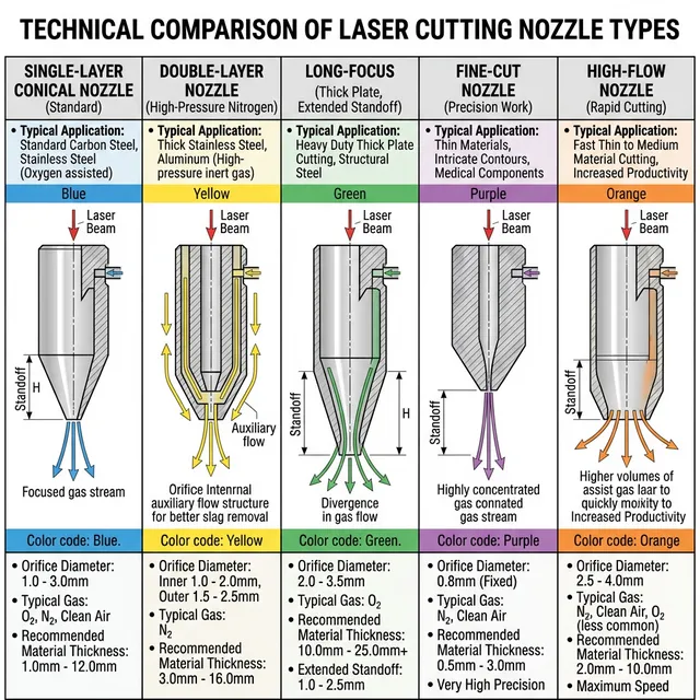
Technical comparison of 5 laser cutting nozzle types
Choose the right nozzle to optimize cut quality, speed, and operational costs
Nozzle Selection Validation Path
Pick nozzle diameter from material, thickness, gas, and target edge quality, then validate gas flow, kerf compensation, standoff, and expected nozzle life before locking the parameter set. If dross, taper, or side-burn appears, change only one of these variables at a time.
Convergent-divergent (Laval) design accelerates gas to supersonic speeds through throat section.
Applications
Thin sheet high-speed cutting (≤3mm)
High-volume production lines
Maximum throughput priority
Advantage: Extremely fast cutting Tradeoff: Expensive, shorter lifespan
Nozzle Cross-Section Diagrams
Single-Layer Nozzle
Simple conical design with single gas channel. Gas flows directly through to the orifice. Most economical option for general cutting applications.
Classification by Material
Material
Thermal Conductivity
Wear Resistance
Typical Life
Cost
Best For
Copper
Excellent
Fair
120h
Low
General cutting, cost-sensitive applications
Chrome-Plated Copper
Excellent
Good
180h
Medium
High-intensity production, best cost-performance ratio
Alloy (Brass/Bronze)
Good
Excellent
240h
High
Extreme conditions, specialized applications
* Lifespan values are typical for standard operating conditions. Actual life varies based on power, material, gas type, and maintenance practices.
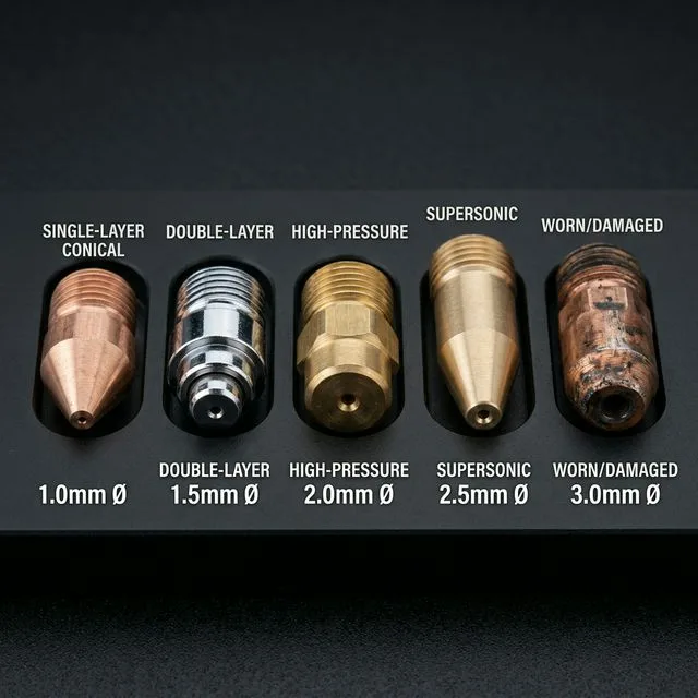
The five main nozzle types side by side — from precision single-layer (1.0mm) to heavy-duty supersonic (2.5mm). The worn nozzle on the right shows why regular inspection matters: orifice deformation causes asymmetric gas flow and cut quality degradation
2. Interactive Nozzle Selector
Not sure which nozzle to choose? Use our interactive decision tree to get personalized recommendations based on your specific cutting requirements.
Interactive Nozzle Selection Guide
Answer a few questions to get personalized nozzle recommendations
1
2
3
4
MaterialThicknessGasResult
Step 1: Select Material Type
3. Nozzle Diameter Selection
Nozzle diameter is critical for cut quality and efficiency. Selecting the correct diameter ensures optimal gas flow, kerf width, and cutting speed.
Diameter Selection by Material and Thickness
Nozzle Diameter
Material Thickness
Assist Gas
Cutting Characteristics
ø 0.8 - 1.0mm
0.5-3mm
Oxygen
Thin sheet high-speed, precision cutting
ø 1.2 - 1.5mm
3-8mm
Oxygen / Nitrogen
General purpose, most common
ø 1.8 - 2.0mm
8-15mm
Oxygen / Nitrogen
Medium-thick plate cutting
ø 2.5 - 3.0mm
15-25mm
Oxygen
Thick plate cutting
ø 3.5 - 5.0mm
25mm+
Oxygen
Ultra-thick plate specialized
Diameter Selection Principles
1.Thinner material = Smaller diameter: Thin sheets benefit from smaller nozzles for concentrated energy and faster speeds
2.Thicker material = Larger diameter: Thick plates require larger nozzles to ensure adequate gas flow and penetration
3.Nitrogen requires larger diameter: Nitrogen cutting typically needs 0.2-0.5mm larger diameter than oxygen for same thickness
4.When in doubt, go larger: Undersized nozzles risk burning out; slightly oversized is safer
Nozzle Diameter vs. Kerf Width
Nozzle Diameter
Typical Kerf Width
Tolerance
Applications
0.8mm
0.08-0.12mm
±0.02mm
Ultra-thin sheet, high precision
1mm
0.10-0.15mm
±0.02mm
Thin sheet, precision cutting
1.2mm
0.12-0.18mm
±0.03mm
General thin to medium sheet
1.5mm
0.15-0.25mm
±0.03mm
Most common general purpose
1.8mm
0.20-0.30mm
±0.04mm
Medium thickness cutting
2mm
0.25-0.35mm
±0.04mm
Medium to thick plate
2.5mm
0.30-0.45mm
±0.05mm
Thick plate cutting
3mm
0.35-0.50mm
±0.05mm
Ultra-thick plate
* Kerf width varies based on laser power, focus position, and cutting speed. Values shown are typical for standard conditions.
4. Standoff Distance & Focal Position
Standoff distance (nozzle tip to workpiece) and focal position are critical parameters that affect cut quality, gas pressure delivery, and collision risk.
Standoff Distance Visualizer
Adjust standoff distance and focal offset to see optimal positioning
Optimal range: 0.5 - 1 mm
0.5 mm3.0 mm
-3 mm0+3 mm
Standoff is within optimal range for Carbon Steel
Standoff Distance
The distance between the nozzle tip and the workpiece surface. Affects gas pressure at the cut point and collision risk.
Focal Offset
Position of the laser focal point relative to the nozzle tip. Negative = above surface, Positive = below surface. Typically 0 to +2mm for cutting.
Material-Specific Standoff Recommendations
Carbon Steel (Oxygen)
Standoff: 0.5-1.0mm
Focal Offset: 0 to +1mm (at or slightly below surface)
Lower standoff maintains gas pressure for oxidation reaction. Watch for spatter adhesion on nozzle.
Stainless Steel (Nitrogen)
Standoff: 0.8-1.5mm
Focal Offset: 0 to +2mm
Slightly higher standoff reduces collision risk. Maintain consistency for quality.
Aluminum (Nitrogen)
Standoff: 1.0-2.0mm
Focal Offset: 0 to +2mm
Higher standoff protects optics from reflection damage. Use anti-reflective nozzle coating if available.
Non-Metals (Air/Nitrogen)
Standoff: 0.5-1.5mm
Focal Offset: -1 to +1mm
Adjust based on material flammability. Control flame with appropriate gas flow.
Capacitive Height Control
How It Works
Capacitive sensors detect the electrical capacitance between nozzle and workpiece. The control system automatically adjusts Z-axis to maintain constant standoff distance, even on warped or uneven materials.
Setup Procedure
Enable capacitive height sensing in control system
Set target capacitance value (corresponds to desired standoff)
Calibrate zero point (nozzle touching workpiece)
Set tracking speed and sensitivity parameters
Test on sample material and verify standoff accuracy
• After nozzle change: Mandatory recalibration required
• After collision: Check sensor and recalibrate
5. Gas Flow & Pressure Requirements
Proper gas flow and pressure are essential for effective cutting. Insufficient flow leads to poor slag removal and oxidation, while excessive flow wastes gas without improving quality.
Gas Flow Rates by Nozzle Diameter
Nozzle Ø
Oxygen Flow
O₂ Pressure
Nitrogen Flow
N₂ Pressure
Air Flow
Air Pressure
0.8mm
40-80 L/min
0.5-0.8 bar
80-120 L/min
8-10 bar
60-100 L/min
6-8 bar
1mm
50-100 L/min
0.5-1.0 bar
100-150 L/min
10-12 bar
80-120 L/min
8-10 bar
1.2mm
80-120 L/min
0.8-1.2 bar
120-180 L/min
10-12 bar
100-150 L/min
8-10 bar
1.5mm
100-200 L/min
1.0-1.5 bar
150-300 L/min
12-15 bar
120-200 L/min
10-12 bar
1.8mm
150-250 L/min
1.2-1.8 bar
250-400 L/min
12-16 bar
180-280 L/min
10-14 bar
2mm
200-350 L/min
1.5-2.0 bar
300-500 L/min
15-18 bar
250-400 L/min
12-16 bar
2.5mm
300-500 L/min
1.8-2.5 bar
500-800 L/min
18-22 bar
400-600 L/min
15-20 bar
3mm
400-700 L/min
2.0-3.0 bar
700-1000 L/min
20-25 bar
500-800 L/min
18-22 bar
* Flow rates and pressures are typical values. Adjust based on material thickness, laser power, and cutting speed. Higher values within range for thicker materials.
Gas Purity Requirements
Oxygen: 99.5%+ purity
Higher purity improves cutting speed and edge quality. Industrial grade sufficient for most applications.
Nitrogen: 99.99%+ purity (4.0 grade minimum)
High purity critical for oxide-free edges on stainless steel. Consider 99.999% (5.0 grade) for best quality.
Compressed Air: Clean, dry, oil-free
Use proper filtration and dryers. Oil contamination damages optics and affects cut quality.
Pressure Optimization Tips
•Start with recommended pressure, then fine-tune based on cut quality
Proper nozzle alignment ensures the laser beam passes through the center of the nozzle orifice. Misalignment causes uneven cuts, increased nozzle wear, and potential damage to the cutting head.
Alignment Procedure
1
Install Nozzle
Thread nozzle onto cutting head and tighten to manufacturer specified torque
Typical torque: 5-8 Nm. Do not overtighten.
2
Red Light Pointer Check
Activate red light pointer and verify beam passes through nozzle center
Red dot should be centered in nozzle orifice when viewed from below
3
Tape Burn Test
Place masking tape over nozzle, fire low power pulse (50-100W, 1-2ms)
Burn mark should be circular and centered. Elliptical or off-center indicates misalignment.
4
Inspect Pattern
Examine burn pattern for concentricity
Perfect circle = aligned. Oval or eccentric = adjust cutting head.
5
Adjust if Needed
Use cutting head adjustment screws to center beam
Refer to cutting head manual for specific adjustment procedure
6
Re-verify
Repeat tape burn test after adjustment
Continue adjusting until burn pattern is perfectly centered
7
Document
Record alignment date and nozzle serial number
Maintain alignment log for quality control
Signs of Misalignment
Cut edge is angled or beveled instead of perpendicular
Inconsistent cut quality around part perimeter
Excessive nozzle wear on one side
Burn marks or damage on nozzle interior
Elliptical instead of circular burn pattern on tape test
Compare different nozzle specifications side-by-side to make informed purchasing decisions. Consider total cost of ownership, not just initial price.
Nozzle Comparison Matrix
Select 2-4 nozzles to compare specifications side-by-side
Specification
Single Layer Copper 1.5mm
Double Layer Chrome-Copper 1.5mm
Type
Single Layer
Double Layer
Material
Copper
Chrome-Plated Copper
Diameter
1.5 mm
1.5 mm
Typical Lifespan
120 hours
234 hours
Cost (USD)
$35
$85
Cost per Hour
$0.29/hr
$0.36/hr
Applications
• General cutting
• Carbon steel 3-8mm
• Cost-sensitive production
• High-quality cutting
• Stainless steel nitrogen
• Production environments
Advantages
Low cost
Widely available
Good thermal conductivity
Longer lifespan
Stable gas flow
Better cut quality
Disadvantages
Shorter lifespan
Less stable gas flow
Higher initial cost
Requires proper maintenance
Comparison Insights
• Best Value: Single Layer Copper 1.5mm (lowest cost per hour)
• Longest Life: Double Layer Chrome-Copper 1.5mm
• Most Economical: Single Layer Copper 1.5mm (lowest initial cost)
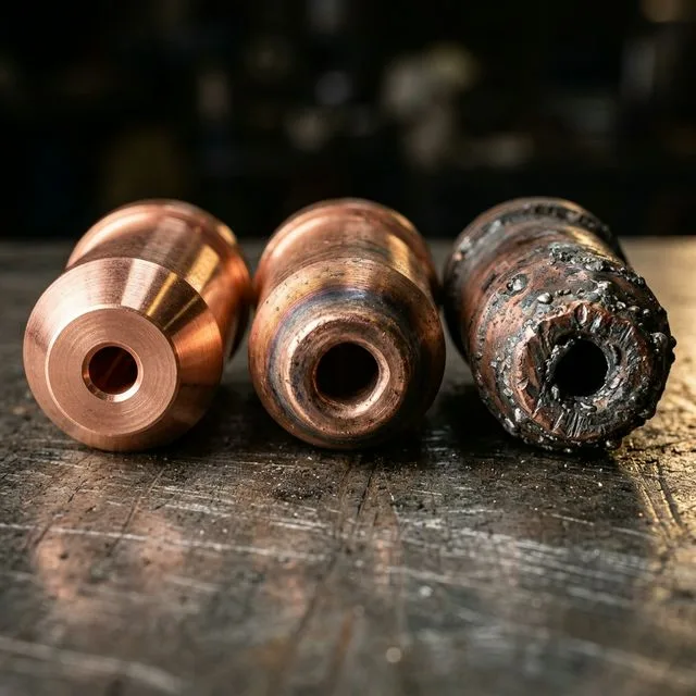
Nozzle wear progression from new (left) to end-of-life (right). Replace when orifice diameter increases >10% or becomes visibly asymmetric — a worn nozzle increases gas consumption by 20-30% while degrading cut quality
8. Maintenance & Lifespan Management
Proper maintenance extends nozzle life and maintains cut quality. Regular inspection and timely replacement prevent production issues and minimize downtime.
Nozzle Wear Progression
Track nozzle condition based on operating hours
Current Usage0 / 120 hours (0%)
0h60h96h120h
New / Good Condition
Nozzle is in excellent condition. Continue normal operation.
Recommended Actions:
•Perform routine cleaning
•Monitor cut quality
•Document usage hours
Wear Stage Timeline
0-50%
New / Good Condition
Optimal performance, routine maintenance only
50-80%
Light Wear
Increased monitoring, plan replacement
80-100%
Heavy Wear
Quality degradation, replace soon
100%+
Replace Immediately
Exceeded lifespan, risk of failure
Inspection Checklist
Inspection Checklist
1.
Visual Inspection
Check for deformation, cracks, burn marks, or spatter buildup
2.
Orifice Diameter Measurement
Use pin gauge or microscope. Replace if diameter increased by 10%
3.
Concentricity Check
Verify laser beam and nozzle orifice alignment with tape burn test
4.
Thread Condition
Inspect threads for wear or damage that could cause loosening
Life Extension Tips
Daily Cleaning
Wipe nozzle exterior with soft cloth to remove spatter
Collision Avoidance
Enable collision detection sensors, set appropriate safety height
Proper Storage
Store in dry, dust-free container to prevent scratches
Scheduled Replacement
Replace proactively before complete failure affects quality
Molten metal spatter adheres to nozzle interior, disrupting gas flow. Prevention: Optimize cutting parameters, use anti-spatter coating, clean regularly
20%
Normal Wear
High-temperature gas flow gradually enlarges orifice diameter over time. Management: Track operating hours, measure diameter regularly, establish replacement schedule
Related Tool
Calculate nozzle lifespan and replacement schedule:
Understanding brand specifications and compatibility helps with sourcing, inventory management, and finding cost-effective alternatives.
Thread Specifications & Compatibility
Brand/Series
Thread Specification
Compatible With
Notes
Precitec ProCutter
M11×1
• WSX M11 series
• Generic M11 nozzles
Most common standard, widely available
Raytools BM Series
M14×1
• Bodor OEM
• Generic M14 nozzles
Second most common, good availability
WSX Standard
M11×1 / M12×1
• Precitec M11 (if M11 thread)
• Generic equivalents
Check specific model, varies by series
Bodor OEM
M14×1
• Raytools BM
• Generic M14 nozzles
Usually compatible with Raytools
Legacy Equipment
M16×1.5
• Older model specific nozzles
Less common, check manufacturer specs
Major Brand Overview
Precitec (Germany)
Premium brand, excellent quality, higher price point. ProCutter series widely used, HighSpeed series for thin sheet applications.
Raytools (Switzerland)
High market share, good cost-performance ratio. BM series general purpose, AG series adaptive nozzles with auto height adjustment.
Chinese Brands (WSX, Bodor, etc.)
Competitive pricing, improving quality. Good option for cost-sensitive applications. Verify thread compatibility before purchasing.
Cross-Brand Replacement Guide
Compatibility Factors
Thread specification must match exactly
Nozzle height (body length) may vary between brands
Standoff distance may need recalibration
Gas flow characteristics can differ slightly
Replacement Tips
Keep spare nozzles from same brand/batch when possible
Test alternative brands on non-critical jobs first
Document any parameter adjustments needed
Consider total cost including performance, not just price
Price Disclaimer: Nozzle prices vary significantly based on supplier, order quantity, and market conditions. Values mentioned in this guide are approximate as of 2026 for reference only. Contact suppliers for current pricing.
10. Troubleshooting Common Issues
Quick diagnostic guide for nozzle-related cutting problems. Identifying root causes early prevents quality issues and equipment damage.
Symptom 1: Angled or Beveled Cut Edge
Likely Cause: Nozzle misalignment (beam not centered in orifice)
Diagnostic Method:Perform tape burn test to check beam centering
Solutions:
Adjust nozzle position or replace nozzle
Check cutting head installation and alignment
Perform optical path centering calibration
Symptom 2: Sudden Quality Degradation
Likely Cause: Nozzle wear or blockage
Diagnostic Method:Visual inspection and orifice diameter measurement
Solutions:
Clean or replace nozzle
Check gas purity and pressure
Verify standoff distance is correct
Symptom 3: Frequent Collision Alarms
Likely Cause: Nozzle deformation or height sensor malfunction
Diagnostic Method:Visual check for deformation, test height sensor response
Solutions:
Replace deformed nozzle immediately
Calibrate capacitive height sensor
Check Z-axis program settings and limits
Symptom 4: Nozzle Burning/Damage
Likely Cause: Laser reflection or undersized nozzle diameter
Diagnostic Method:Check nozzle interior for burn marks and scoring
Solutions:
Use larger diameter nozzle
Review cutting parameters (power, speed) for appropriateness
For reflective materials, use anti-reflective nozzles
Increase standoff distance for aluminum/copper
Symptom 5: Excessive Spatter on Cut Edge
Likely Cause: Incorrect gas pressure or nozzle standoff
Diagnostic Method:Check gas pressure gauge, measure standoff distance
Solutions:
Increase gas pressure within recommended range
Adjust standoff distance (typically reduce for more pressure)
Verify nozzle orifice is not clogged
Consider switching to double-layer nozzle for better gas flow
Precitec Technical Manuals - ProCutter and HighSpeed nozzle series specifications
Raytools Product Catalogs - BM series and adaptive nozzle technical data
Industry standards and best practices from laser cutting professionals
Field data from production environments and equipment manufacturers
Last Updated: January 15, 2026 Disclaimer: This guide provides general recommendations based on industry standards and manufacturer specifications. Actual parameters may vary based on specific equipment, material conditions, and application requirements. Always consult your equipment manufacturer's documentation and perform test cuts before production runs. LaserSpecHub is not responsible for cutting quality or equipment damage resulting from parameter selection.